TOYOTA COASTER · LIGHT KIT INSTALLATION
JULY 2026, Version 2
Which kit does this guide apply to?
This installation guide covers the internal-mount SafeBus School Bus Light Kit for the Toyota Coaster, compliant in every Australian state and territory except NSW and Tasmania.
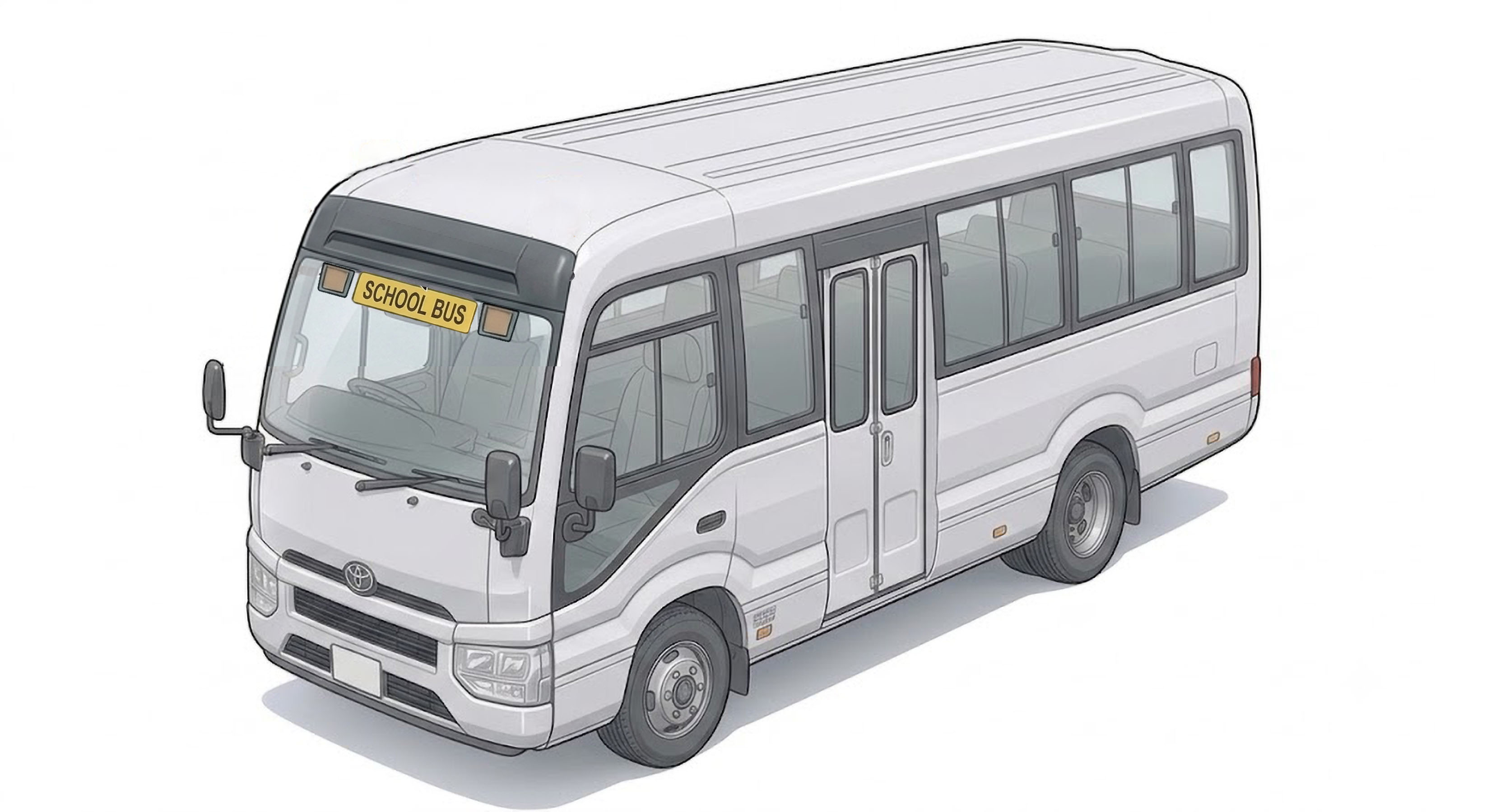
FRONT:
Internal mount
· REAR:
Internal mount
Toyota Coaster (2017+)
School Bus Light Kit — Installation Guide
!
Before you start
- Read every step in full before beginning any wiring or drilling.
- Disconnect the battery negative terminal before making any connections.
- Two-person job recommended when feeding the loom through the headlining and A-pillar.
- Always verify door-sensor polarity (Section 2.4) with a multimeter before connecting — incorrect polarity will not trigger the warning lights correctly.
Kit items
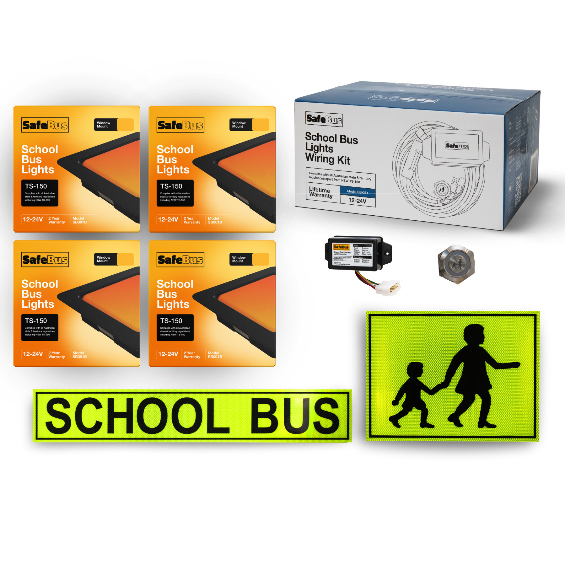
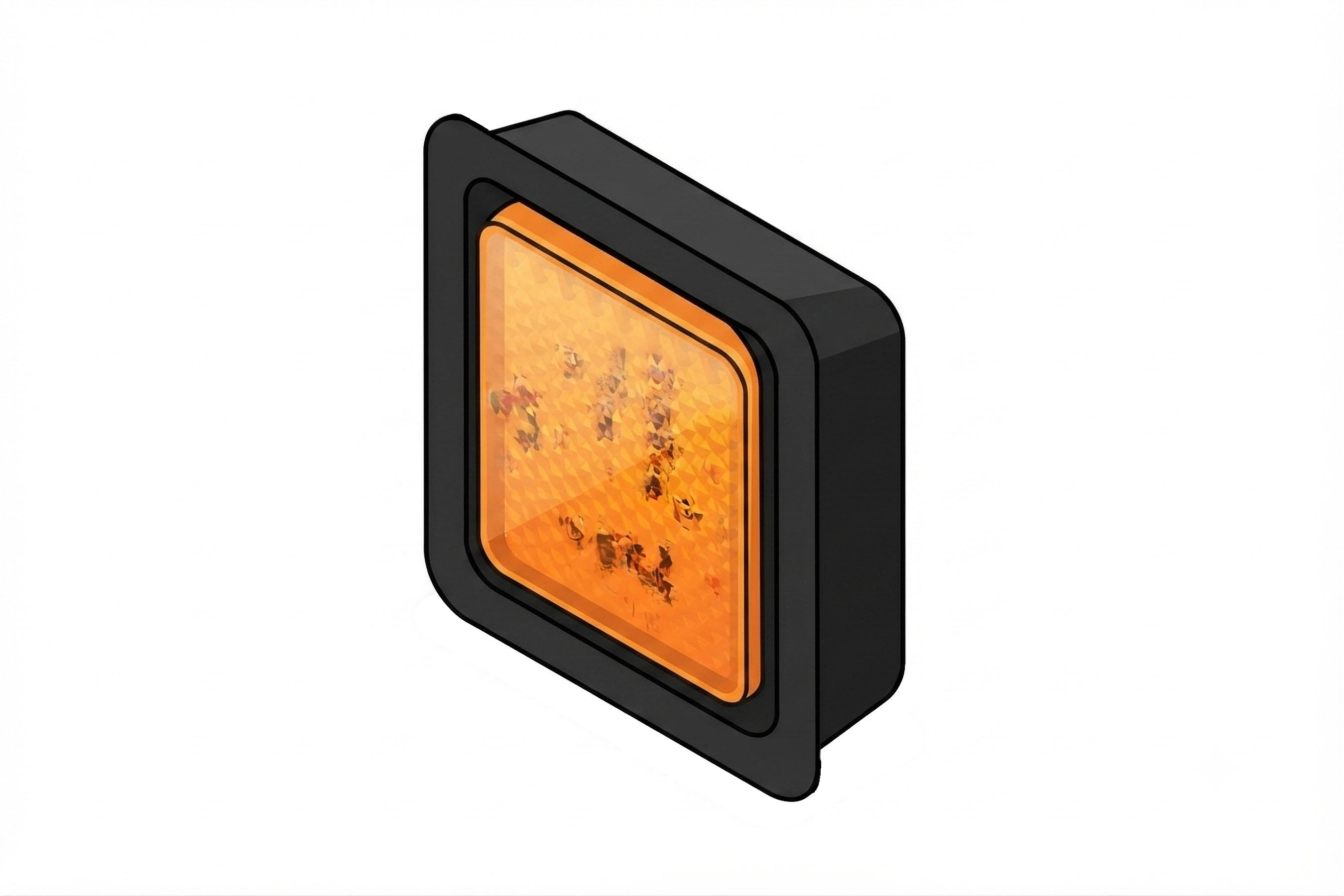
- SB001B Front Wig-Wag lights
- SB001B Rear Wig-Wag lights
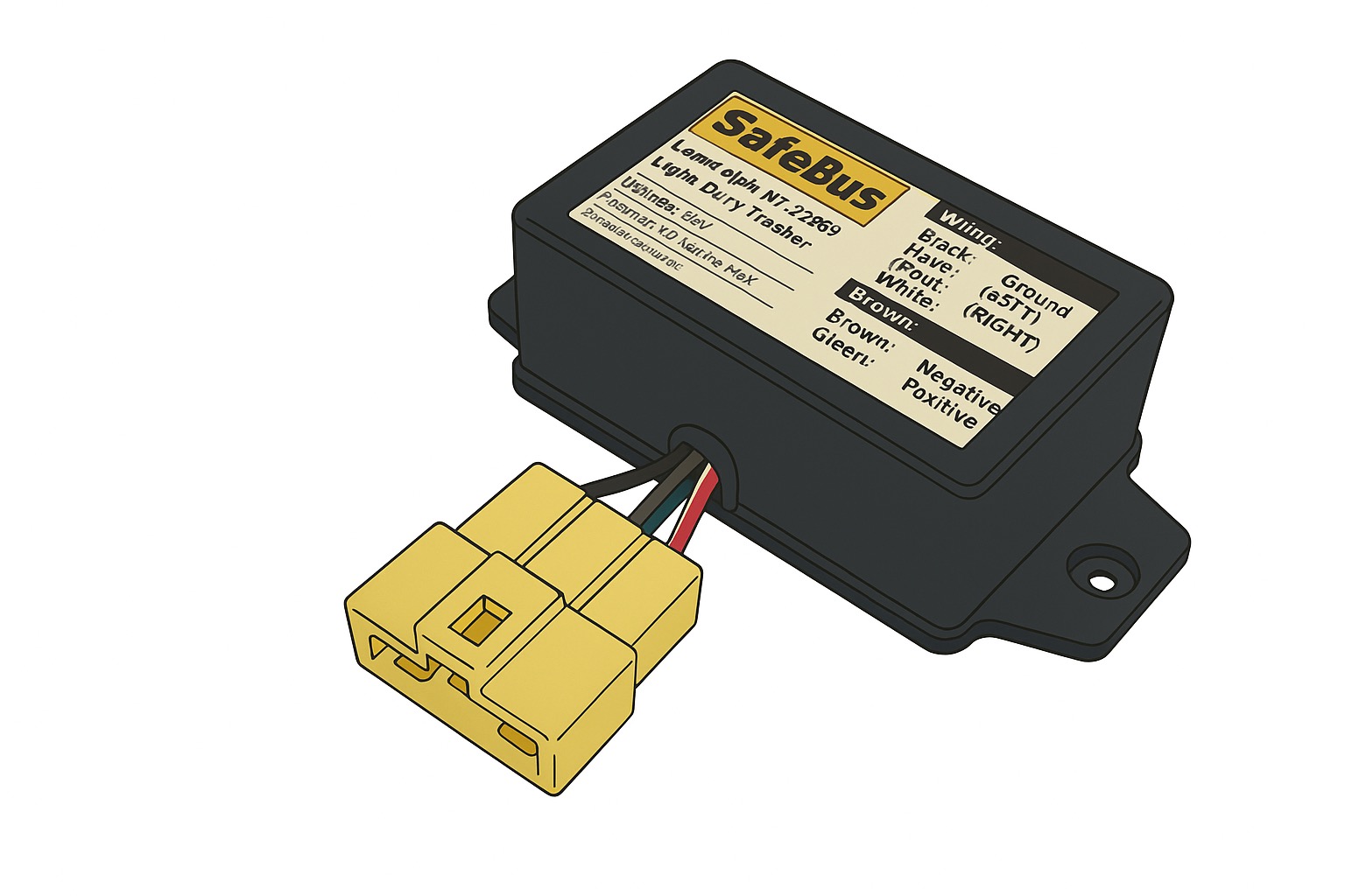
- LCM100 Electronic control box
- SBKIT1 Complete loom
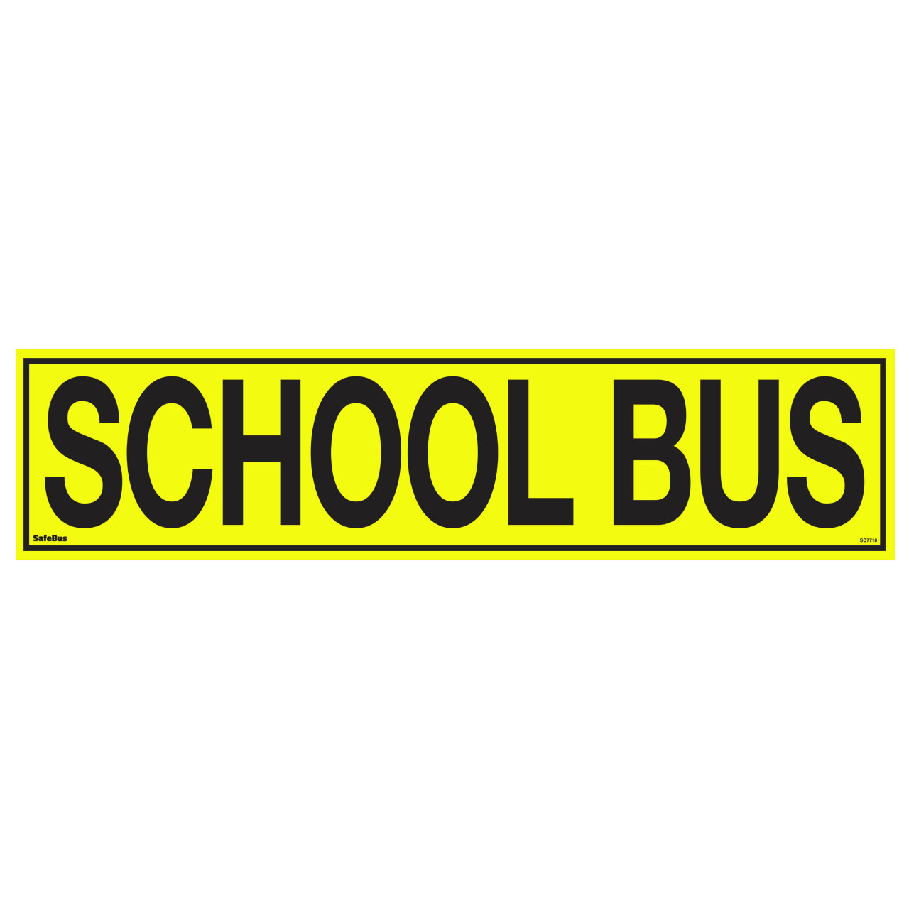
- SB7718 Front signage
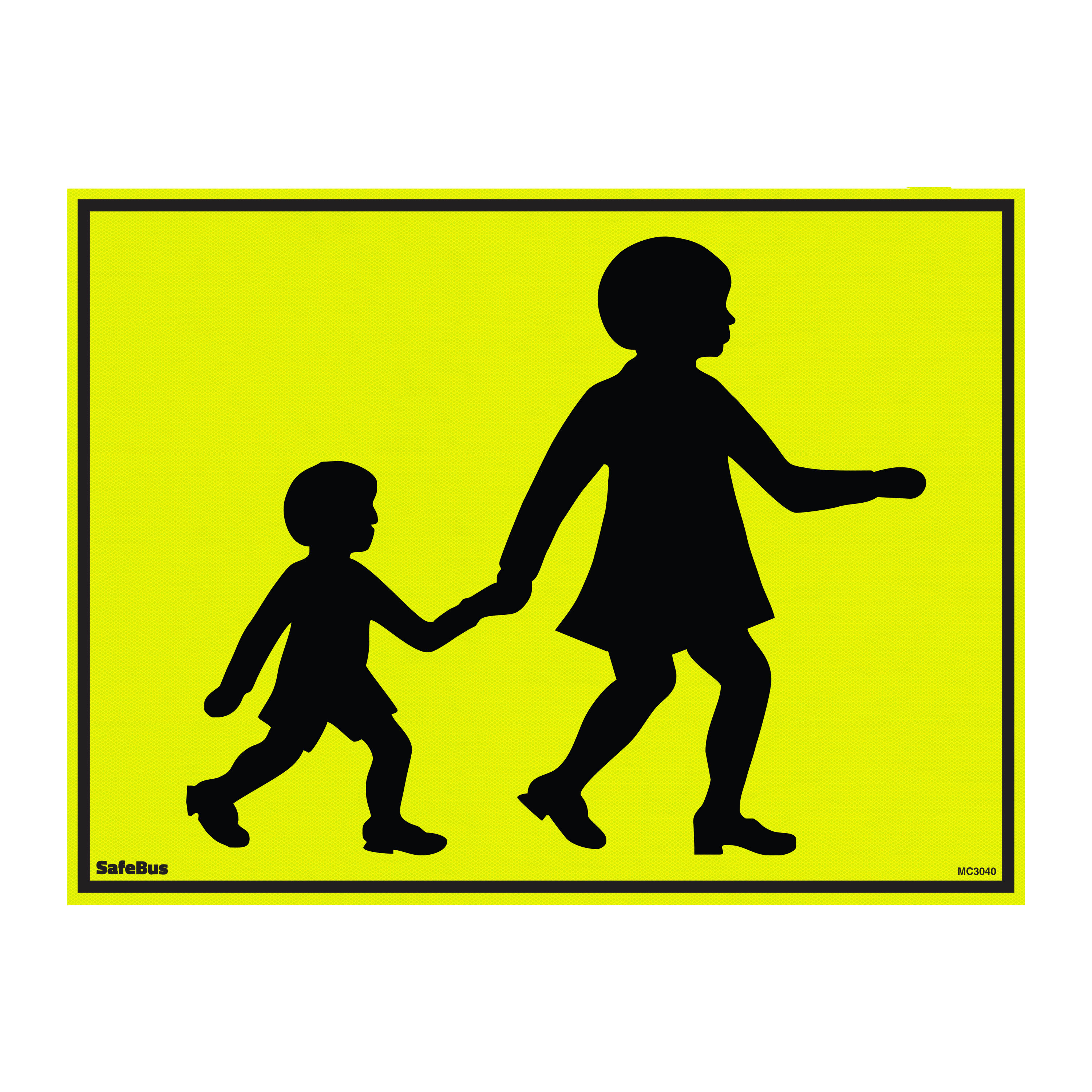
- MC3040 Rear signage
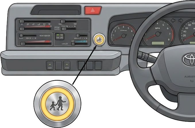
- Dash switch
- Door sensor assembly
Tools & materials
- 18–20mm hole saw
- Wire strippers & terminal crimper
- Cable ties
- Trim removal tool
- Multimeter (polarity check)
- Supplied 2-pin & 3-pin connectors
Package Contents
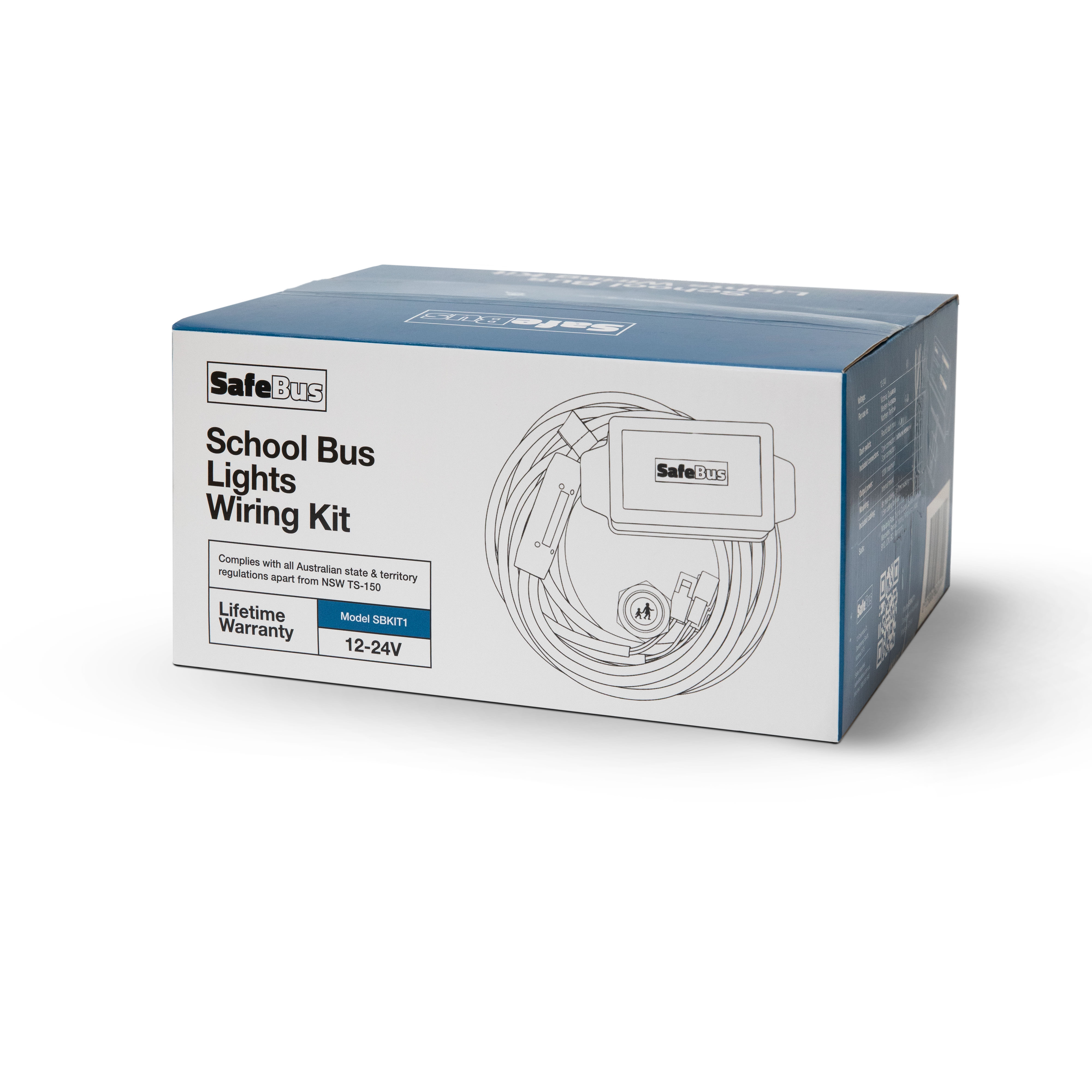
Suggested cable runs


Tip: to make loom installation easier, cut it at the white tag markers, feed it through the bus, then rejoin using the supplied 3-pin connectors.
1
Signage & lights
1.1 — Front signage & lights
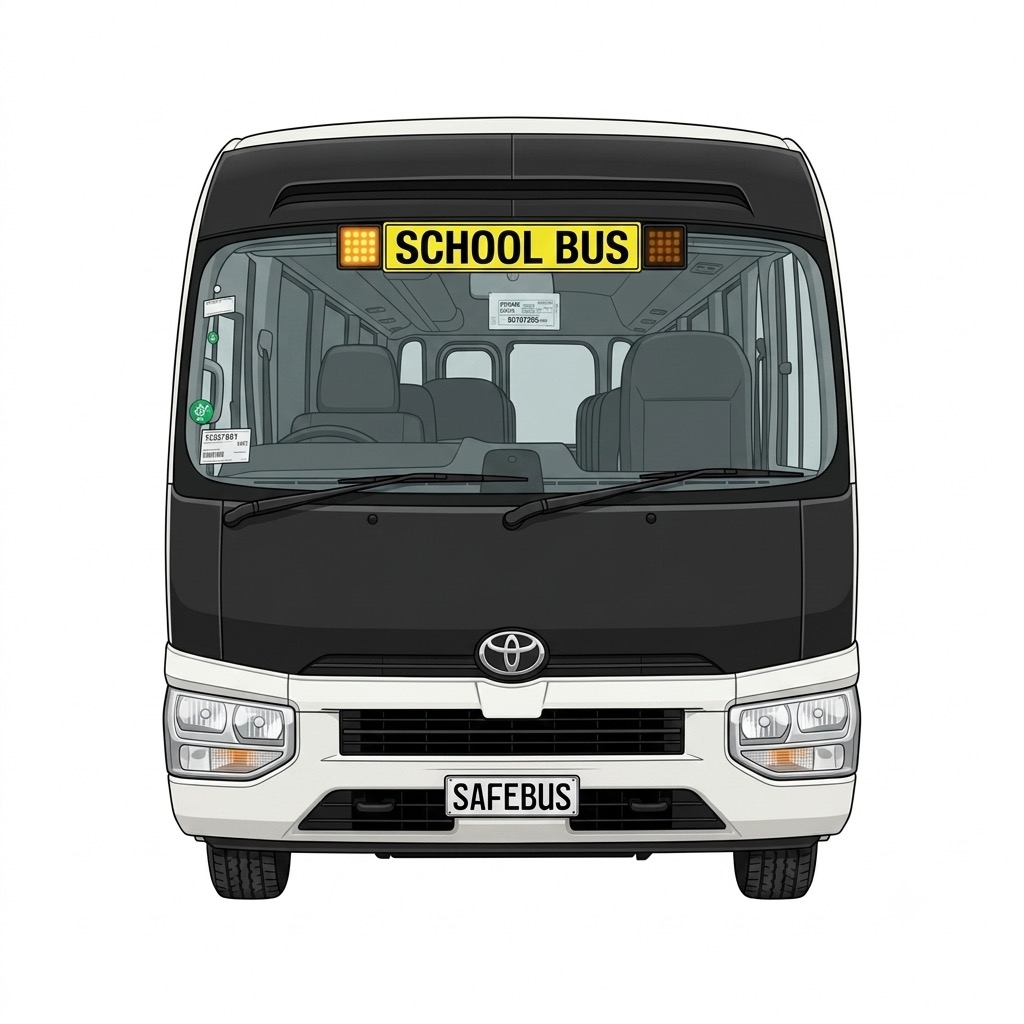
- Stick the SCHOOL BUS sign centrally at the top of the windscreen, see Fig 3 for reference.
- From the inside of the windscreen, attach the SB001B front lights on either side of the SCHOOL BUS signage, mounting them within 100mm of the sign.
- Run the cables from the lights up into the headlining
- Remove the climate vent above the driver. Locate the light cables that were inserted through the headlining and pull them through.
- Use the supplied 2-pin connectors to connect the lights to the main loom (see Step 2 for loom runs)
1.2 — Rear signage & rear lights
- As there are barn doors at the back of the Coaster, cut the decal to the right of the foot of the larger figure on the decal & attach on the right side of the bus (driver's side). See Fig. 4 for reference
- Stick the lights on the inside of the rear glass, making sure that both lights are no more than 100mm away from the decal & the same distance to the decal. The right side light will fit comfortably in the small panel, see Fig 4 for reference.
- Right light: run the cable inside the trim around the window. Left light: open the right barn door and remove the lower door trim and blue plastic. Drill 3 holes as per Fig 5. Stick the light to the glass & run cables inside the door frame and then through to the bus.
- Connect the lights to the main loom using the supplied 2-pin connectors


2
Wiring
Tip: Refer to Fig 1 for additional information on suggested cable runs before starting
2.1 — Front to back
- Remove the plastic trim around the glove box and A-pillar moulding.
- Run the loom from the top of the A-pillar to the rear of the bus through the headlining or air vents. This is typically the point where the loom is cut and rejoined with the 3-pin connectors.
- At the rear of the bus, the loom may also be cut to ease passage through to the rear lights
2.2 — Glove box area
- Below the glove box, connect the black GND wire to ground.
- One power option is below the glove box. Connect the red +V wire to a fuse in the fuse box. Check with a multimeter for ignition power.
- Connect the supplied 6-way connector to the switching box.
2.3 — Switch
- Using an 18–20mm hole saw, cut a hole in the dash and insert the supplied switch. See Fig 6 for suggested position
- Connect the switch to the grey connector
2.4 — Door sensor
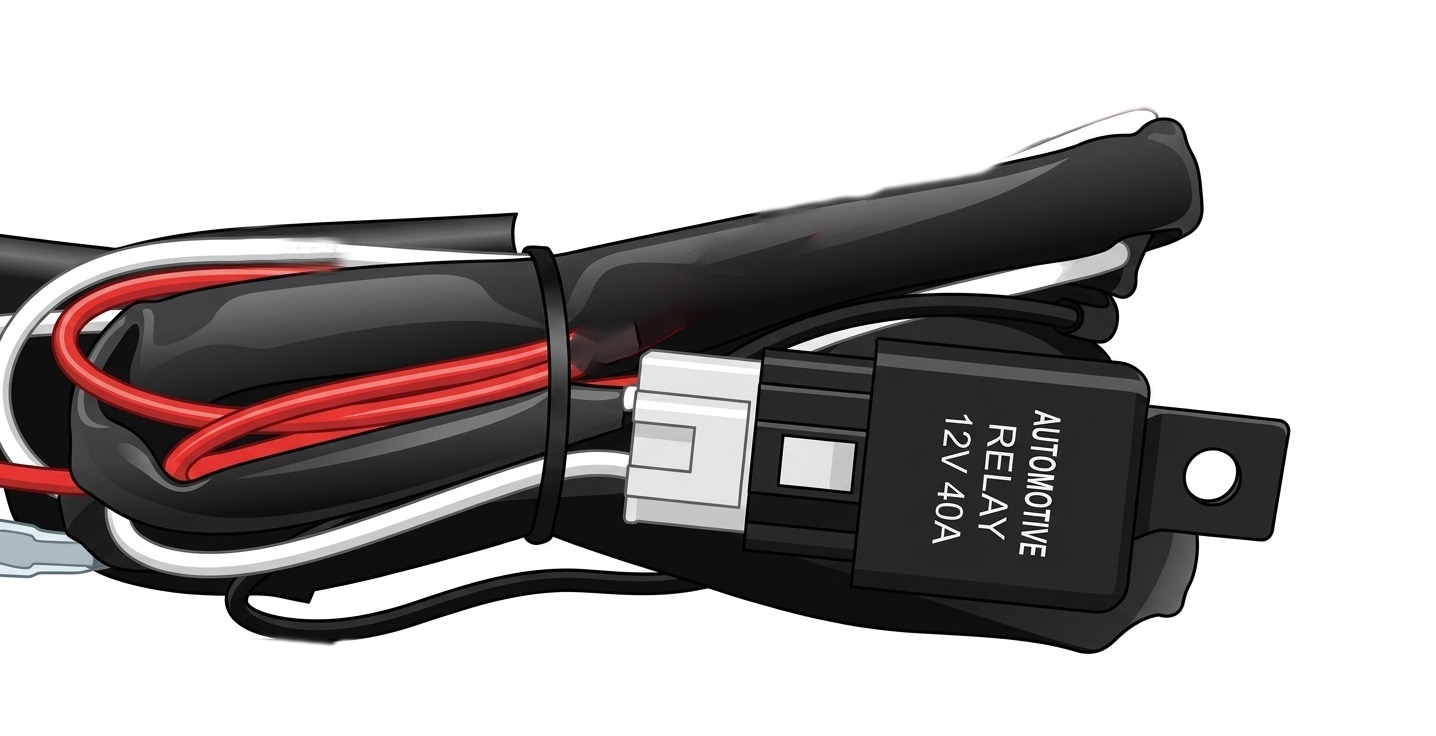
The door sensor is connected via the supplied relay. Connect the black wire to ground and run the twin core cable to the light near the swing/concertina door footwell. Connect the red wire to one side of the light and the black wire to the other side.
Reference — flashing controller wiring
| Wire | Function |
|---|---|
| Red | Positive |
| Black | Ground |
| Yellow | Left light |
| White | Right light |
| Brown | Door sensor — negative |
| Green | Door sensor — positive |

SafeBus · 1300 391 848 · safebus.com.au
For professional installation only