LDV DELIVER 9 · LIGHT KIT INSTALLATION
JULY 2026, Version 2
Which kit does this guide apply to?
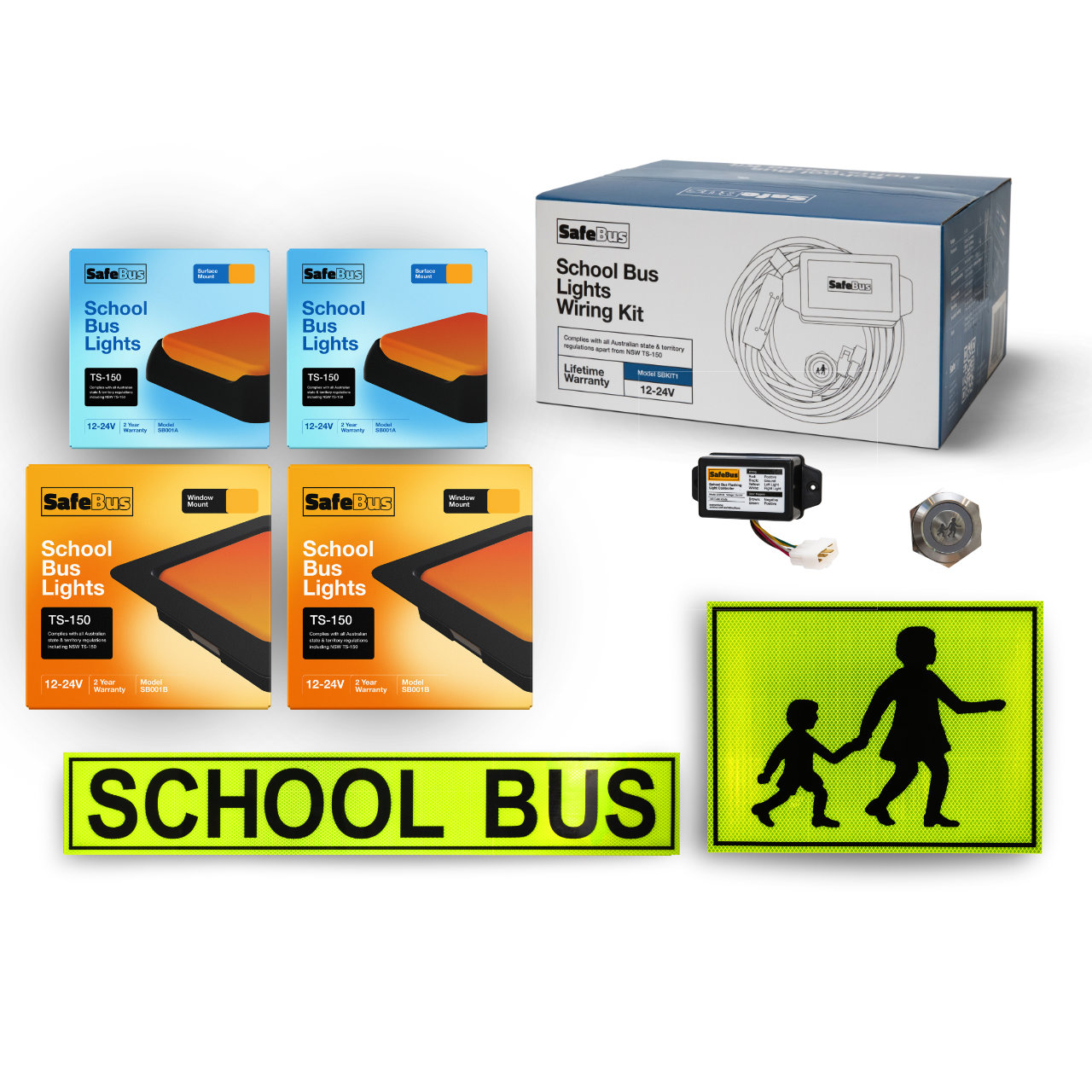
This installation guide covers the mixed-mount (front internal, rear external) SafeBus School Bus Light Kit for the LDV Deliver 9, compliant in every Australian state and territory except NSW and Tasmania. Pick your state below to view and order the correct kit.
FRONT:
Internal mount
· REAR:
External mount
LDV Deliver 9
School Bus Light Kit — Installation Guide
!
Before you start
- Read every step in full before beginning any wiring or drilling.
- Disconnect the battery negative terminal before making any connections.
- Two-person job recommended when feeding the loom through the headlining and A-pillar.
- Always verify door-sensor polarity (Section 2.4) with a multimeter before connecting — incorrect polarity will not trigger the warning lights correctly.
Kit items
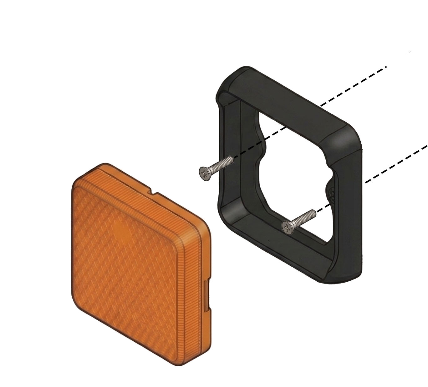
- SB001B Front Wig-Wag lights
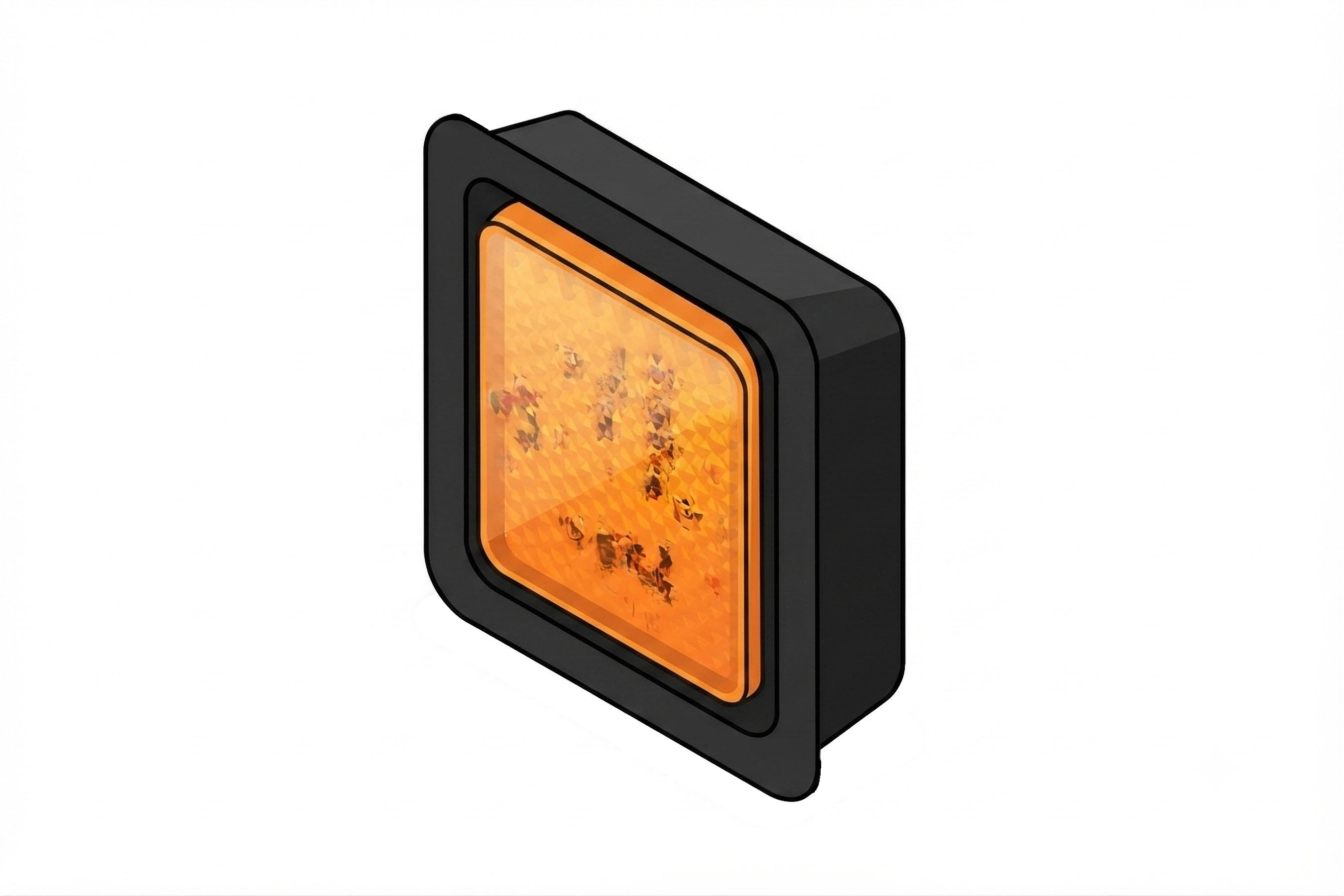
- SB001A Rear Wig-Wag lights
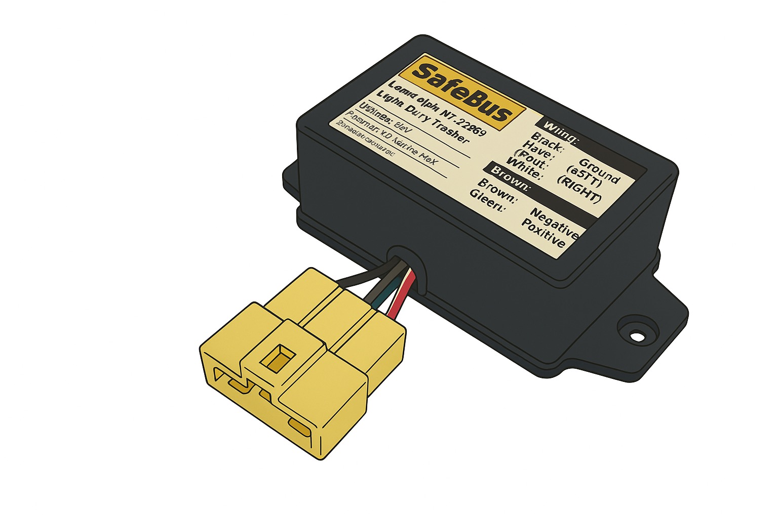
- LCM100 Electronic control box
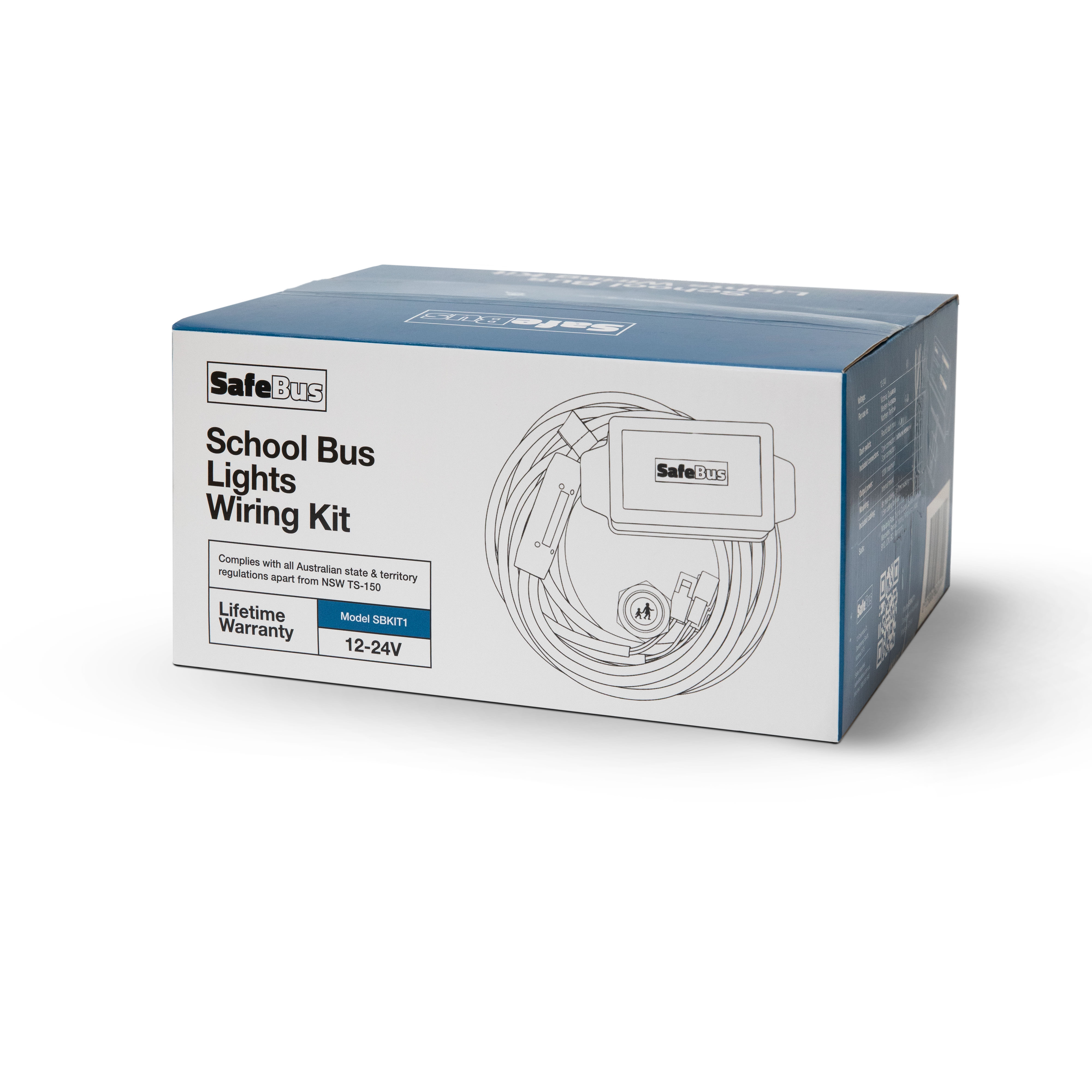
- SBKIT1 Complete loom
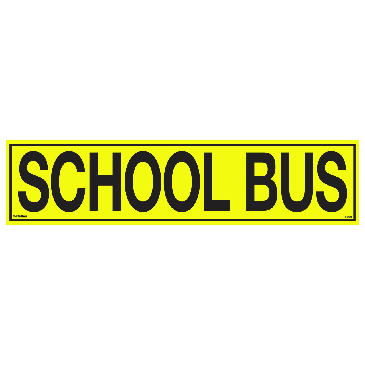
- SB7718 Front signage
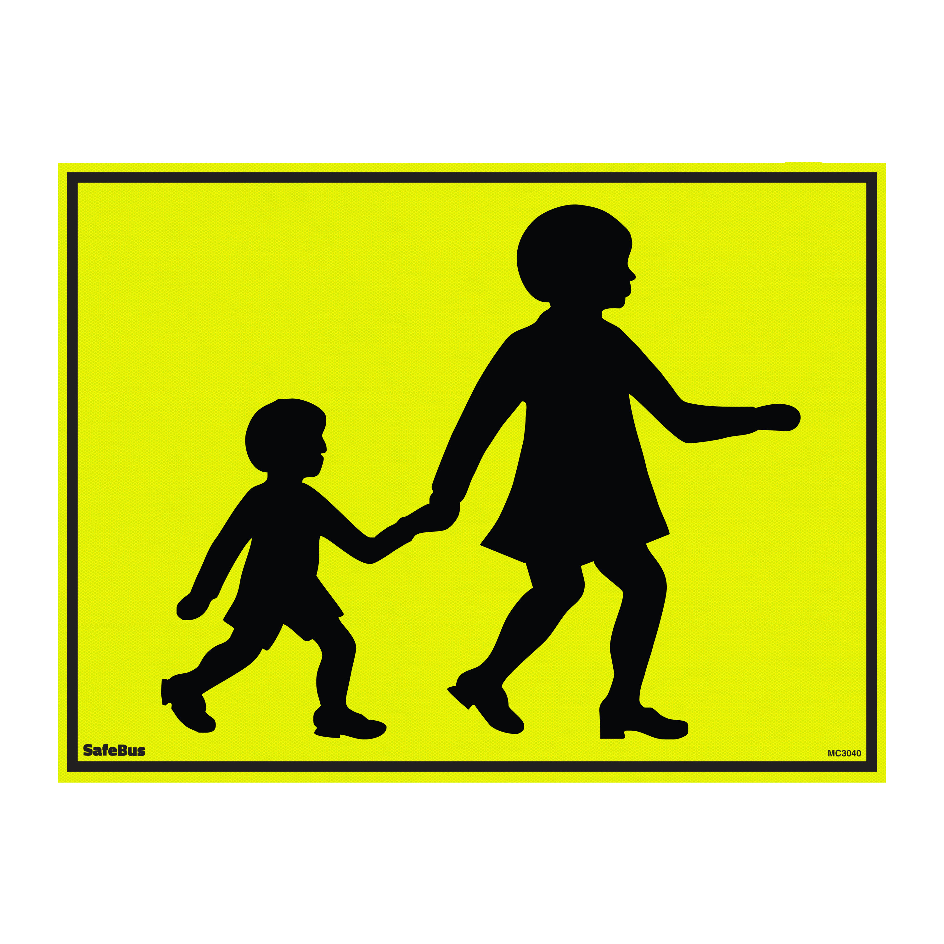
- MC3040 Rear signage
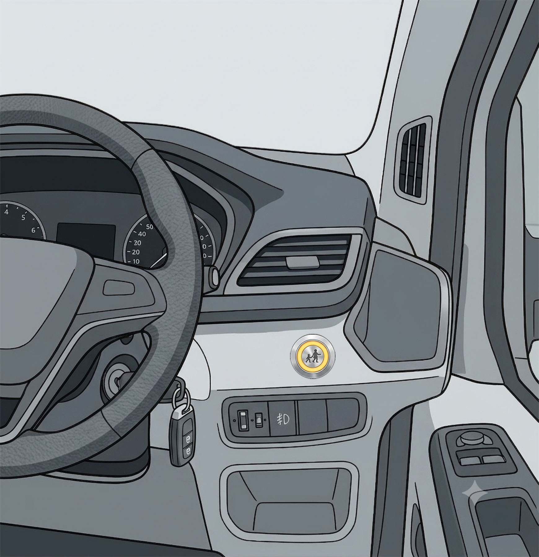
- Dash switch
- Door sensor assembly
Tools & materials
- 18–20mm hole saw
- Wire strippers & terminal crimper
- Cable ties
- Trim removal tool
- Multimeter (polarity check)
- Supplied 2-pin & 3-pin connectors
Package Contents
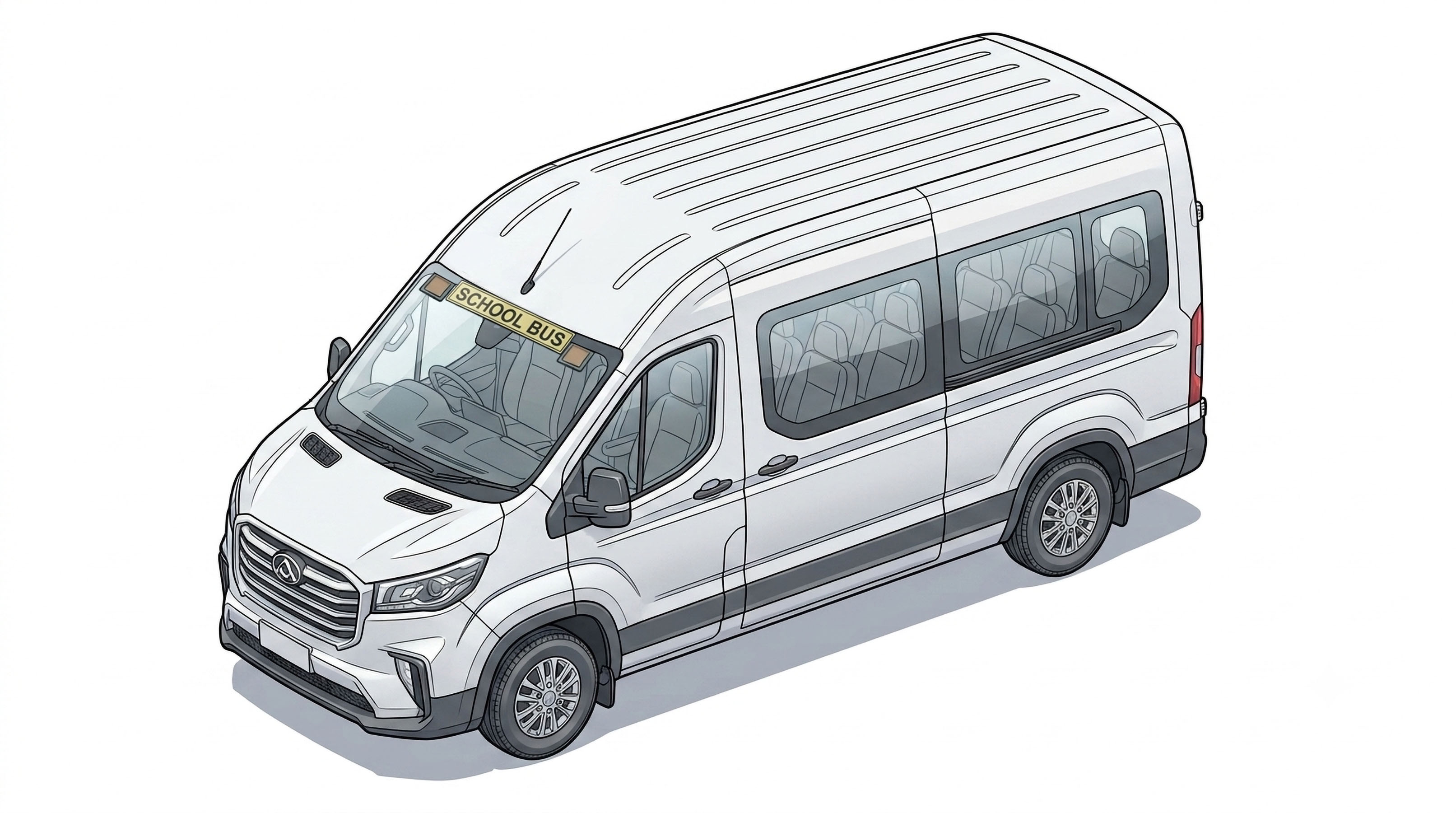
Suggested cable runs


Tip: to make loom installation easier, cut it at the white tag markers, feed it through the bus, then rejoin using the supplied 3-pin connectors.
1
Signage & lights
1.1 — Front signage & lights
- Stick the SCHOOL BUS sign at the very top of the windscreen.
Note: Some models have an ADAS camera in this area that may require trimming of the sign - On the inside of the windscreen attach the SB001B front lights on either side of the SCHOOL BUS signage, mounting them within 100mm of the sign and visually confirm that they are level with the road.
- If possible, make sure the top flange of the light is under the headliner. Run the cables through the headliner to the driver's side A-pillar
- Use the supplied 2-pin connectors to connect the lights to the main loom (see Step 2 for loom runs)

1.2 — Rear signage & rear lights
- As there are barn doors at the back of the LDV, cut the decal in half & attach as per Fig. 3
- Attach the SB001A lights above the rear glass, making sure that both lights are no more than 100mm away from the decal & the same distance to the decal. See Fig 3 for reference.
- Open both barn doors and remove the trim pieces. Run the light cables down through the door frame and out to the rubber boot connecting the door to the bus chassis. See Fig 4 for details
- Connect the lights to the main loom using the supplied 2-pin connectors.
Note: light cable extension may be required


2
Wiring
Tip: Refer to Fig 1 for additional information on suggested cable runs before starting
2.1 — Front to back
- To the right of the steering wheel, remove the cup holder and trim covering the fuse panel. Mount the LCM100 module in this area.
- Run the loom from the fuse panel area to the top of the A-pillar to the rear of the bus through the headlining or air vents. This is typically the point where the loom is cut and rejoined with the 3-pin connectors.
- At the rear of the bus, the loom may also be cut to ease getting the cables through the rubber boots to the rear lights.
2.2 — Switch
- Using an 18–20mm hole saw, cut a hole in the dash and insert the supplied switch. See Fig 6 for suggested position
- Connect the switch to the grey connector
2.3 — Door sensor
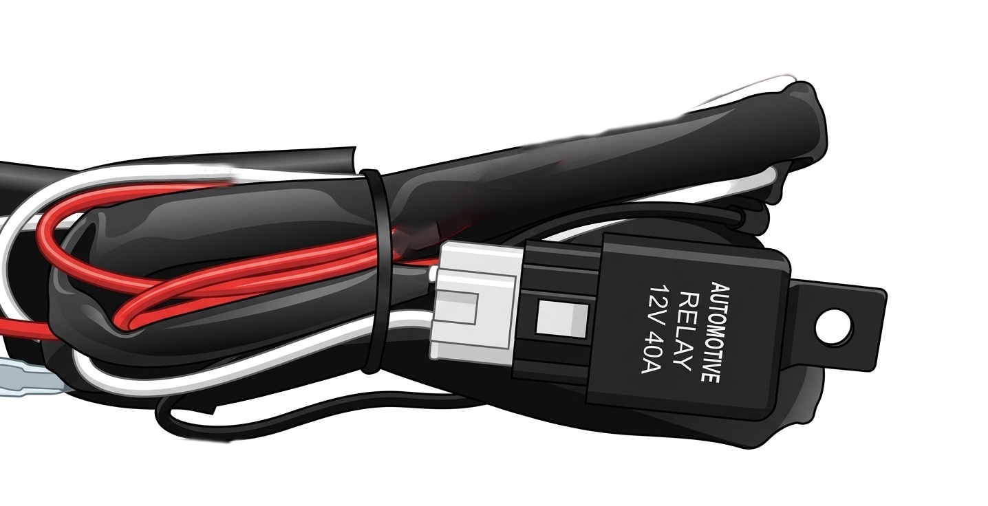
The door sensor is connected via the supplied relay. Mount the relay near the LCM100 and connect the black wire to ground and run the twin core cable to the light near the sliding door footwell. Connect the red wire to one side of the light and the black wire to the other side. See Fig 5.
Note: When the bus has been sitting idle for some time or the door has been left open, the light may go off. During normal pick-up & drop off operation, it will function correctly.

Reference — flashing controller wiring
| Wire | Function |
|---|---|
| Red | Positive |
| Black | Ground |
| Yellow | Left light |
| White | Right light |
| Brown | Door sensor — negative |
| Green | Door sensor — positive |

SafeBus · 1300 391 848 · safebus.com.au
For professional installation only